
LXLZ Note: This Product Provides Solutions for Parameter Customization And Application.
5-Stage EMI Filter Wire Leads Maximum Noise Suppression
If you've ever dealt with equipment failing EMC compliance tests, or watched sensitive machinery behave erratically because of line noise, you already know how much a proper EMI filter matters. This isn't just a passive component — it's the difference between a product that passes certification and one that doesn't ship.
The CW4L5-R series is a 5-stage single-phase AC power line EMI filter built for engineers and OEM procurement teams who need reliable, repeatable noise suppression across a wide range of industrial and commercial applications. With current ratings from 1A to 40A and a working voltage of 250V AC (50/60Hz), this filter covers the vast majority of single-phase equipment configurations you'll encounter in real production environments.
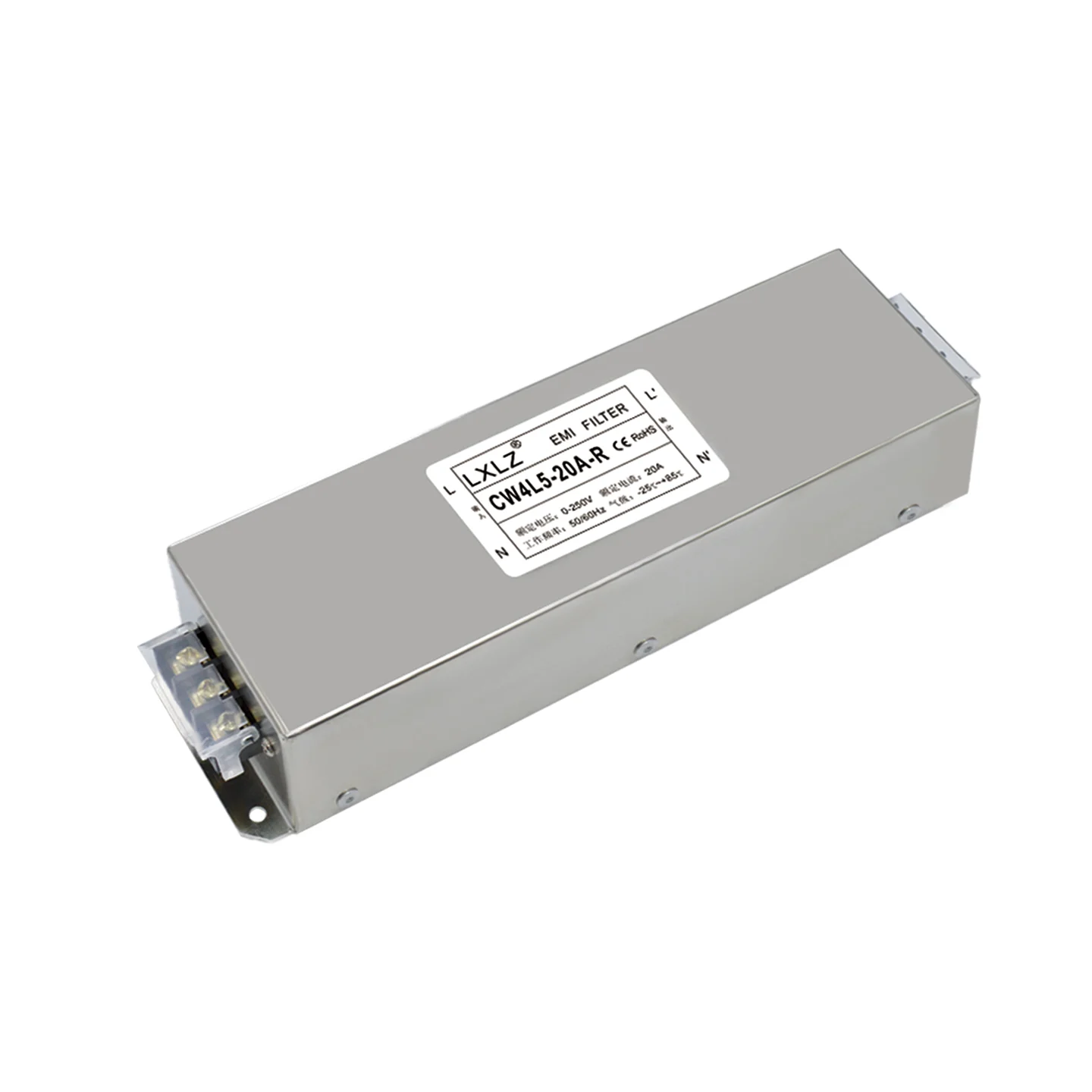
The terminal block (screw-type) connection interface shown in the product image makes panel integration straightforward — no crimping tools required, and the connection points are clearly labeled (L, N, L', N') directly on the housing label, reducing wiring errors during assembly.
Table of Contents
Key Specifications at a Glance
| Parameter | Details |
|---|---|
| Model Series | CW4L5-R (e.g., CW4L5-20A-R shown) |
| Filter Type | Single-Phase, 5-Stage |
| Rated Voltage | 0–250V AC |
| Frequency | 50 / 60 Hz |
| Current Range | 1A / 3A / 6A / 10A / 16A / 20A / 30A / 40A |
| Connection Type | Terminal Block (Screw Terminal) |
| Operating Temp | -25°C to +85°C |
| Certifications | CE, RoHS |
| Interference Suppression | EMI / RFI (Common Mode + Differential Mode) |
| Housing | Steel enclosure, panel-mount flanges on both ends |
What the 5-Stage Design Actually Does for You
Most budget EMI filters use a 1- or 2-stage LC network. They work — to a point. But when your equipment needs to pass EN 55032, CISPR 22, or FCC Part 15 requirements, a single stage often isn't enough attenuation, especially in the 150kHz–30MHz range where switching power supplies and motor drives generate the most interference.
The 5-stage topology in the CW4L5 series stacks multiple LC filter sections in series. Here's what that means in practice:
- Deeper attenuation across a broader frequency band — each stage adds insertion loss, and the combined effect is significantly better suppression than single or dual-stage alternatives
- Both common-mode and differential-mode noise are addressed — the design handles interference traveling between line and neutral (differential) as well as between live conductors and ground (common mode)
- Better protection in both directions — noise generated by your equipment is blocked from polluting the grid; noise coming from the grid is blocked from reaching your sensitive loads
For applications like variable frequency drives (VFDs), CNC controllers, medical equipment power inputs, industrial automation panels, and switching power supply assemblies, this level of filtering is often the deciding factor in whether a product gets CE marked or sent back for redesign.
Construction & Integration Highlights
From the product image, a few things stand out that matter to procurement and engineering teams:
- Compact rectangular steel housing — the all-metal enclosure provides shielding in addition to the passive filtering, which compounds the suppression performance. The gray powder-coat finish is clean and corrosion-resistant.
- Dual mounting flanges — visible on both ends of the unit, these allow secure panel mounting with standard screws. The unit sits flush and stable inside an enclosure.
- Transparent terminal block cover — the screw terminal interface is protected by a clear plastic shield, which prevents accidental contact and keeps the connection secure in vibration-prone environments.
- Clear labeling on housing — model number, voltage, current rating, frequency, and temperature range are printed directly on the label. For assemblers working on a production line, this matters more than people give it credit for.
- CE and RoHS marked — confirmed on the housing label, which simplifies documentation for export products destined for EU markets.
Typical Applications
This filter series is a practical fit for:
- Industrial automation equipment — PLCs, servo drives, motion controllers
- Variable frequency drives (VFDs) / inverters — one of the most common sources of conducted EMI on AC lines
- CNC machinery and machining centers
- Medical device power inputs (where leakage current specs of the specific model must be confirmed)
- Telecommunications and broadcast equipment racks
- EV charging station control boards
- Laser cutting and welding power systems
- Industrial power supplies and UPS systems
- Test and measurement equipment
Best Practices from the Field
After supporting OEM customers across automation, power electronics, and industrial equipment sectors, here's what actually makes a difference when deploying these filters:
- Mount as close to the power entry point as possible. The longer the unfiltered cable run inside your enclosure, the more it acts as an antenna. Ideally, the filter sits right at the AC inlet.
- Bond the filter housing to chassis ground with a short, low-impedance connection. A long ground wire defeats the common-mode suppression. Use a star washer or direct metal-to-metal contact where possible.
- Keep input and output wiring physically separated. Running the "dirty" input side and "clean" output side in the same cable bundle re-couples the noise you just filtered out. Separation of even 5cm makes a measurable difference.
- Match your current rating with margin, not at the edge. For a 15A load, use the 20A variant. Running a filter at its rated maximum continuously shortens component life and affects performance.
- For VFD applications, pair the filter with shielded cable on the motor side — the filter handles the supply-side conducted emissions, but the motor cable is a radiation source that needs separate treatment.
- Verify leakage current requirements before use in medical or touch-accessible applications. Standard industrial EMI filters have leakage current levels that may not comply with IEC 60601 without additional review.
FAQ
Can you supply test reports or insertion loss curves for the filter?
Yes. As a manufacturer, we can provide insertion loss data measured per CISPR 17 methodology. If you need data at specific frequencies for your compliance documentation, contact us with your requirements and we'll supply the relevant curves for the current rating you're sourcing.
What current ratings are available, and can we get custom ratings?
The standard range covers 1A, 3A, 6A, 10A, 16A, 20A, 30A, and 40A. For OEM projects requiring non-standard ratings or modified filter topology, we support custom development — typically with MOQ and tooling discussion upfront. Reach out with your target specs.
What are the MOQ and lead times for bulk orders?
Standard stock variants (particularly 10A, 20A, 30A) are available with short lead times. For larger blanket orders or specific non-stock variants, lead time is typically 2–4 weeks depending on volume. We can discuss stocking arrangements for high-volume OEM customers.
Are these CE certified, and do you provide documentation for our compliance files?
Yes, CE and RoHS compliance is confirmed (visible on the unit label). We can provide Declaration of Conformity and test reports to support your product compliance documentation. If your target market requires additional certifications (UL, TÜV, etc.), contact us to discuss the specific variant.
Can the filter housing be customized — labeling, mounting configuration, or connector type?
For OEM customers with volume commitments, we support private label printing on the housing, modified mounting flange configurations, and alternative connection interfaces. This is handled on a project basis. Share your enclosure drawings or interface requirements and we'll assess feasibility.
Ready to discuss specifications, samples, or volume pricing? Send us your application details and current rating requirements — we'll respond within one business day.