
LXLZ Nota: Este producto proporciona soluciones para la personalización de parámetros y su aplicación.

Enhanced AC Line Filter DIN Rail Low Leakage EMC Filter
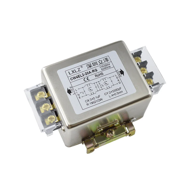
El CW4EL2-RG Series is an enhanced-performance, low leakage current, DIN rail-mountable single phase AC power line EMI filter — combining the superior EMI suppression capability of LXLZ's "E" Enhanced filter platform with the installation convenience of a factory-integrated 35mm DIN rail mounting assembly.
Manufactured by LXLZ (Shenzhen Lize Electronics), the CW4EL2-RG is engineered for industrial control panels and automation enclosures where two performance requirements converge: higher EMI attenuation than standard filters provide, and lower leakage current than conventional filter designs permit. This combination makes the CW4EL2-RG the correct specification choice for applications where both EMC compliance margin and ground leakage current limits are active design constraints — including medical adjacent equipment, IT infrastructure, and sensitive industrial control systems.
Table of Contents
Specifications
| Parámetro | Details |
|---|---|
| Model Series | CW4EL2-RG — Enhanced / Low Leakage / DIN Rail |
| Phase | Single Phase |
| Rated Voltage | 115VAC / 250VAC |
| Frecuencia | 50Hz / 60Hz |
| Current Rating | 1A / 3A / 6A / 10A / 16A / 20A / 30A |
| Connection Type | Terminal Block — Wire Lead (LINE / LOAD) |
| Mounting Type | 35mm DIN Rail Mount (EN 60715 TS35) |
| DIN Rail Bracket | Zinc-Plated Steel Clip with Adjustment Screw |
| Terminal Material | Gold-Plated Copper |
| Terminal Protection | Transparent Protective Cover |
| LINE Terminals | L / N / E (3-position block) — Left Side |
| LOAD Terminals | Multi-position block — Right Side |
| Housing | Nickel-Plated Steel — Wide Body |
| Filter Grade | Enhanced — "E" Series / Low Leakage |
| Filter Topology | Dual-Stage π-Type LC Circuit |
| CX Capacitor | 3 × 0.1μF |
| CY Capacitor | 2 × 3300pF |
| Inductance | 4 × 0.5mH |
| Bleed Resistor | 1MΩ / 1/2W |
| Certification | CE / RoHS |
📄 Full datasheet, leakage current specification, insertion loss curves, and dimensional drawings available upon request.
Three Performance Pillars — What CW4EL2-RG Delivers
Pillar 1 — Enhanced EMI Suppression ("E" Grade)
El "E" prefix in CW4EL2 designates the Enhanced performance grade — a measurably higher insertion loss specification compared to standard CW4L2 series filters.
| Attribute | Standard Grade | Enhanced "E" Grade |
|---|---|---|
| Insertion Loss Level | Standard | Higher attenuation |
| Common-Mode Suppression | Good | Superior |
| Differential-Mode Suppression | Good | Superior |
| EMC Compliance Margin | Minimum compliant | Greater margin above threshold |
| Target Environment | General industrial | Demanding / high-noise environments |
Pillar 2 — Low Leakage Current Design
El "L" in CW4EL2 specifically designates the Low Leakage current design characteristic — a critical parameter distinct from standard EMI filters.
Why Leakage Current Matters:
In standard EMI filters, Y-class capacitors (CY) connected line-to-earth and neutral-to-earth are the primary common-mode suppression elements — but they also create a path for leakage current to flow to earth ground at the power frequency (50/60Hz). In standard designs, this leakage current can reach levels that:
- Trip residual current devices (RCDs / GFCIs) — causing nuisance tripping in protected circuits
- Exceed safety limits for equipment connected to sensitive power distribution systems
- Create personnel safety concerns in accessible equipment installations
- Violate leakage current limits specified in medical, IT, and commercial equipment safety standards
The CW4EL2-RG's Low Leakage design controls CY capacitor values and circuit architecture to maintain effective common-mode suppression while keeping ground leakage current within tightly controlled limits — enabling deployment in environments where standard high-leakage filters cannot be used.
Pillar 3 — DIN Rail Installation Efficiency
El "RG" suffix denotes the DIN Rail (R) with Clip (G) mounting configuration — factory-integrated for direct snap-on installation onto standard 35mm EN 60715 TS35 DIN rails in IEC-standard control panels and enclosures.
Installation benefits:
- No panel drilling required
- No additional mounting brackets
- Snap-on engagement in seconds
- Locking screw prevents vibration-induced disengagement
- Repositionable without panel modification
Circuit & Internal Component Details
Capacitor Network
- CX (X-Class, Differential-Mode): 3 × 0.1μF X-rated line-to-line capacitors attenuating differential-mode conducted EMI — switching transients, harmonic currents, and high-frequency differential noise. X-capacitors do not contribute to ground leakage current
- CY (Y-Class, Common-Mode): 2 × 3300pF Y-rated capacitors optimized for the Low Leakage design target — providing effective common-mode noise suppression while controlling the 50/60Hz leakage current contribution to within the specified low leakage limit. CY value selection is the primary leakage current control parameter in this design
Inductor Network
- L: 4 × 0.5mH Enhanced Common-Mode Choke High-permeability toroidal core winding — within the Enhanced "E" platform, inductor performance is optimized in conjunction with the CY-controlled circuit to achieve the higher insertion loss target without relying solely on CY capacitance for common-mode attenuation. This topology allows effective EMI suppression with reduced CY values — directly enabling the low leakage current characteristic
Bleed Resistor
- R: 1MΩ / 0.5W X-capacitor discharge resistor — safely dissipates stored charge after AC power disconnection within the time window required by IEC 60335 and EN 60950 safety standards
Product Features
Enhanced + Low Leakage — Dual Performance Advantage
The CW4EL2-RG is the correct specification when both higher EMI attenuation AND controlled leakage current are required simultaneously — a combination that standard EMI filters cannot deliver. This dual performance characteristic opens deployment in:
- Environments with RCD/GFCI protected distribution circuits
- Equipment with strict leakage current certification limits
- Multi-filter installations where cumulative leakage current is a design constraint
- Sensitive power distribution systems in healthcare, IT, and laboratory environments
Industrial DIN Rail Mounting — Zinc-Plated Steel Clip
- Zinc-plated steel clip with adjustment locking screw — industrial-grade retention for demanding panel environments
- Compatible with EN 60715 standard 35mm TS35 DIN rail — universal IEC panel rail standard
- Locking screw engagement prevents clip disengagement under vibration, cable pull, and thermal cycling
- Tool-assisted installation — snap on, tighten screw, wire — complete in under 90 seconds
- Enables flexible panel layout positioning without enclosure modification
Wide-Body Nickel-Plated Steel Housing
- Enlarged body accommodates the enhanced component assembly — higher-performance inductors and optimized capacitor network
- Fully enclosed construction — maximum EMI shielding effectiveness
- Nickel plating — corrosion resistance and reliable chassis ground bonding contact
- Robust mechanical construction for sustained industrial panel service life
Gold-Plated Terminal Blocks with Transparent Safety Covers
- Gold-plated copper terminals — minimal contact resistance, oxidation-free long-term performance at rated current
- Transparent protective covers — live terminal protection and contamination prevention
- 3-position LINE terminal block (L/N/E) — full earth continuity through the filter
- Multi-position LOAD terminal block — accommodating higher current cable cross-sections
- Clear directional labeling — eliminates wiring polarity errors
Dual Voltage: 115VAC / 250VAC
Single product variant covers both North American (115V/60Hz) and international (220–250V/50Hz) power standards — no region-specific inventory variants required
Low Leakage Current — Application Impact
Where Low Leakage is a Specification Requirement
RCD / GFCI Protected Circuits Residual current devices trip at leakage current thresholds (typically 30mA for personnel protection, 10mA or lower for equipment protection). In installations with multiple EMI filters on a shared RCD-protected circuit, cumulative leakage current from standard filters can trigger nuisance tripping. The CW4EL2-RG's low leakage design allows multiple units to operate on the same protected circuit without exceeding the RCD trip threshold.
Medical Adjacent & Healthcare Environments IEC 60601-1 and related medical equipment standards impose strict touch current and leakage current limits on equipment used in or near patient care areas. While the CW4EL2-RG is not itself a medical-certified component, its low leakage characteristic enables integration into equipment designs targeting medical safety standards without the filter becoming the limiting factor in leakage current budgets.
IT Equipment & Data Infrastructure IEC 62368-1 (replacing IEC 60950-1) specifies leakage current limits for IT and AV equipment. In high-density equipment installations, cumulative filter leakage from multiple units in a rack or cabinet can challenge compliance. Low leakage filters reduce the per-unit contribution to the total leakage current budget.
Sensitive Industrial Control Systems High-impedance analog measurement and control systems can be affected by leakage current flowing through ground paths. Low leakage filter designs reduce ground-referenced interference contributions in sensitive measurement environments.
Why Source From Our Factory
In-House Enhanced & Low Leakage Engineering
The "E" enhanced performance and "L" low leakage characteristics are achieved through our own engineering — circuit topology design, component selection, and in-house validation. We manufacture:
- Custom toroidal inductor core winding
- Full enclosure fabrication and surface treatment
- DIN rail clip fabrication and zinc treatment
- In-house leakage current measurement and insertion loss verification
OEM & ODM Capability
- Custom leakage current targets — tighter limits for specific certification requirements
- Custom insertion loss performance — enhanced circuit tuning for demanding EMC standards
- Custom current ratings — 1A to 30A and beyond
- Modified DIN rail configurations — alternative rail profiles or mounting orientations
- Private label branding — full OEM nameplate and documentation customization
- Application-specific engineering — filter design optimized for specific load types, standards, and leakage budgets
Quality Control & Testing
| Test Item | Specification |
|---|---|
| Hi-Pot (Dielectric Withstand) | 1500VAC Line-to-Ground / 1 min |
| Insulation Resistance | ≥ 100MΩ @ 500VDC |
| Leakage Current | Per Low Leakage specification limit |
| Insertion Loss | Per Enhanced grade specification |
| DIN Rail Clip Retention | Mechanical pull-off force verification |
| Terminal Torque | Per block specification |
| Visual & Mechanical | 100% per unit |
Leakage current measurement performed on every production batch — confirming the Low Leakage specification is consistently met in production output, not only in engineering validation samples.
Certificaciones
- ✅ CE Certified — EMC Directive 2014/30/EU & LVD 2014/35/EU
- ✅ RoHS Compliant — EU Directive 2011/65/EU
- 🔄 Additional certifications available on program request
Order & Lead Time
| Order Type | Lead Time |
|---|---|
| Sample (1–5 pcs) | 3 – 7 business days |
| Small Batch (Stock Models) | 7 – 12 business days |
| Volume Order | 12 – 22 business days |
| Custom / OEM Program | 20 – 35 business days |
Mixed current-rating orders accepted within single PO. Shipping: DHL / FedEx / UPS | Sea & Air freight for volume orders Documentation: Invoice, packing list, CO, CE declaration, leakage current and insertion loss test reports
Suitable Buyer Profiles
✔ Industrial Panel Builders & System Integrators Building DIN rail control panels on RCD-protected distribution circuits — where cumulative leakage current from multiple standard EMI filters would cause nuisance tripping or exceed enclosure leakage limits
✔ OEM Equipment Manufacturers with Dual EMC & Leakage Requirements Designing products that must simultaneously meet high EMI attenuation targets and strict leakage current limits — requiring a filter that addresses both constraints without compromise
✔ Medical & Healthcare Facility Equipment Suppliers Specifying power line filtering for non-medical equipment deployed in healthcare environments where leakage current control is a facility-level requirement
✔ IT & Data Infrastructure Equipment Manufacturers Integrating EMI filters into IT equipment designs where IEC 62368-1 leakage current limits constrain filter selection
✔ Electronics Distributors Serving Technical Industrial Markets Expanding catalog with a premium enhanced/low leakage DIN rail EMI filter — differentiated from commodity standard-grade products by dual performance specifications with supporting test documentation
✔ Engineering Procurement Teams Qualifying a factory-direct, CE-certified supplier capable of providing leakage current test data and enhanced insertion loss performance documentation for demanding application specifications
Installation Notes
⚠️  Verify DIN rail is EN 60715 standard 35mm (TS35)
    profile before installation.

⚠️  After snap-on rail engagement, tighten the
    zinc clip locking screw to prevent
    vibration-induced disengagement.

⚠️  Connect LINE terminal block (L/N/E) to AC
    power source input only.
    Connect LOAD terminal block to protected
    equipment output only.
    Incorrect connection degrades filter performance.

⚠️  Bond E terminal and filter housing to panel
    chassis ground. Without ground connection,
    both common-mode suppression and low leakage
    current performance are non-functional.

⚠️  In RCD-protected installations, verify total
    cumulative leakage current from all connected
    filters does not approach the RCD trip threshold.
    Contact our engineering team for leakage
    budget calculation assistance.

⚠️  Tighten all terminal screws to specified torque.
    Replace transparent terminal covers after
    wiring before panel energization.

⚠️  Use cable cross-sections rated for the selected
    current per local electrical installation codes.